|
|
|
|||
|
|
PMA-P PMC-to-PCI Adapter Board |
Features
|
|||
 |
|||||
|
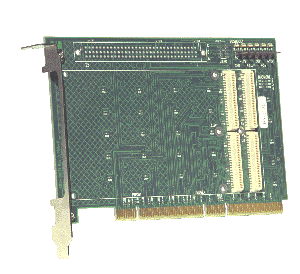
The PMA-P is a single slot PMC-to-PCI adapter board. It enables any 32-bit or 64-bit PMC (PCI Mezzanine Card) module to be plugged into a standard PCI slot. It provides the full 64-bit interconnect between the PCI bus and the PMC connector set. The PMA-P is designed to function as a transparent extension to the PCI bus. As such, it is a passive adapter board and has no PCI-to-PCI bridge. Thus, the carrier’s PCI bus is connected directly to the PMC card’s PCI bus. Because this results in long PCI traces, it is best not to use more than one PMA-P in a backplane segment, and it should be installed in the end slot of the backplane, farthest from the CPU. It is best to avoid use of the PMA-P in a 66 MHz PCI system. Please see the bridged version, PMB-P, for applications requiring use at 66 MHz. To aid in debugging, the PMA-P has Test Point pins and LED indicators for BUSMODE1, +12V, -12V, +5V, +3.3V and VIO. It also has a connector for the JTAG port. PMC Index Pin holes are provided for both 3.3V and 5V PMC signaling pins so that the PMA-P can be configured for either bus environment. Jumpers can be installed to enable 66 MHz mode, and to set PCI PRSNT and PMC BUSMODE.
An optional VME P2-type connector can be included which “breaks
out” the User I/O signals on the PMC Pn4 connector. The
PMA-P provides optional local 3.3V generation because many
PCI bus machines do not supply it. |
|||||
| Home I Products I Support I About Us I Partners I Contact Us I Legal Notice I Site Map I Search | |||||